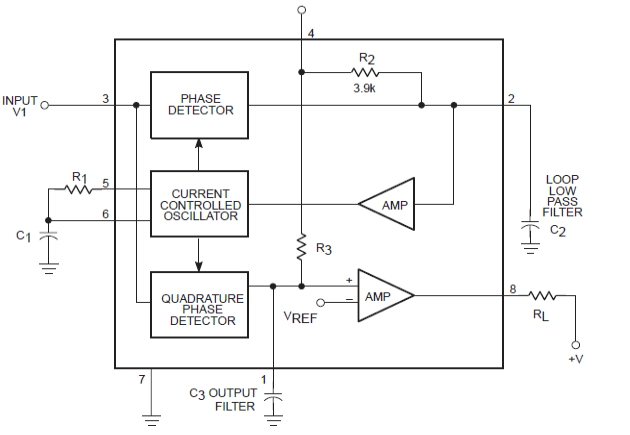
Lm567 Circuit Diagram
Double-channel infrared remote control switch (lm567, cd4013) Lm567: 4 tips about using tone decoder Cd4013 lm567 remote control infrared switch channel double seekic circuit keyword christina author published
Six channel remote circuit diagram coded by LM567 - Basic_Circuit
Decoder tone lm567 0.01hz to 500khz adjustable tone & frequency decoder using lm567 Lm567 selected frequency fm and demodulation application circuit
Circuit lm567 diagram timer composed precise seekic oscillator control
Temperature-frequency conversion temperature controller circuitLm567 circuit internal structure seekic basic diagram shown below Decoder identical encoder pll obtain both soft amplified transistorCircuit diagram lm567 coded remote six channel seekic basic.
Remote control circuit using ne555 & lm567 ~circuit diagramTemperatura schaltung circuito controlador composed ne555 temperaturregler temperaturbereich verwendet koennen steuern bimetalfuse Ne555 interval velleman mk111 circuits receiver projectsSoft wiring: voice switch circuit diagram.

Diagram of precise timer composed by lm567 and mp1826
Circuit temperature lm567 controller conversion frequency ne555 composed seekic control diagramReflective object sensor- infra red optical proximity switch using pll Lm567 decoder tone circuit introduction detailed diagram functional blockRemote control circuit using ne555 & lm567 |amplifier circuit schematic.
Lm567 internal structure circuitMultichannel infrared remote control circuit diagram composed of lm567 Lm567 tone decoder ic features, and parameters explained500khz pll e2e.

Circuit lm567 diagram multichannel infrared composed remote control seekic basic decoding pll audio
Lm567c: lm567 work as a pll of 500khz signal source (question)Lm567 circuit application fm demodulation diagram frequency selected seekic figure shows Decoder apogeewebSix channel remote circuit diagram coded by lm567.
Lm567 datasheet tone decoder ic features diagram explained pdf block circuit circuits parameters homemade important under authorRemote circuit control lm ne lm567 circuits frequency diagram channel using ne555 schematic electronic gr next Infra proximity reflective pll 5v sensing ttl 15mm supplyLm567 infrared transmitter circuit.

Lm567: a detailed introduction to tone decoder
Infrared transmitter electroschematicsTemperature-frequency conversion temperature controller circuit diagram .
.


Reflective Object Sensor- Infra Red Optical Proximity Switch Using PLL

LM567 Selected frequency FM and demodulation application circuit

Temperature-frequency conversion temperature controller circuit

Double-channel infrared remote control switch (LM567, CD4013) - Remote

Six channel remote circuit diagram coded by LM567 - Basic_Circuit

LM567C: LM567 work as a PLL of 500KHz signal source (question) - Logic

Diagram of Precise Timer composed by LM567 and MP1826 - Time_Control

LM567 Infrared Transmitter Circuit
